Routine Operations
This document describes routine operations that may be performed during the operation of the Galbot robot to ensure all functions work properly.
Map Engine - Mapping & Localization
The map engine is the core foundation of the navigation function. It is not an optional add-on, but a mandatory prerequisite for navigation. Before using the navigation function, you must complete mapping and ensure localization is running properly. Failure to complete mapping and localization correctly will result in the navigation function not working.
Mapping Process
Mapping is a prerequisite for navigation. You must complete the construction of an environment map before using the navigation function.
1. Prerequisites Check (Required)
Check whether the LiDAR service is running
Mapping requires the LiDAR service to be running. Enter the following command on the HPU terminal to check the LiDAR process:
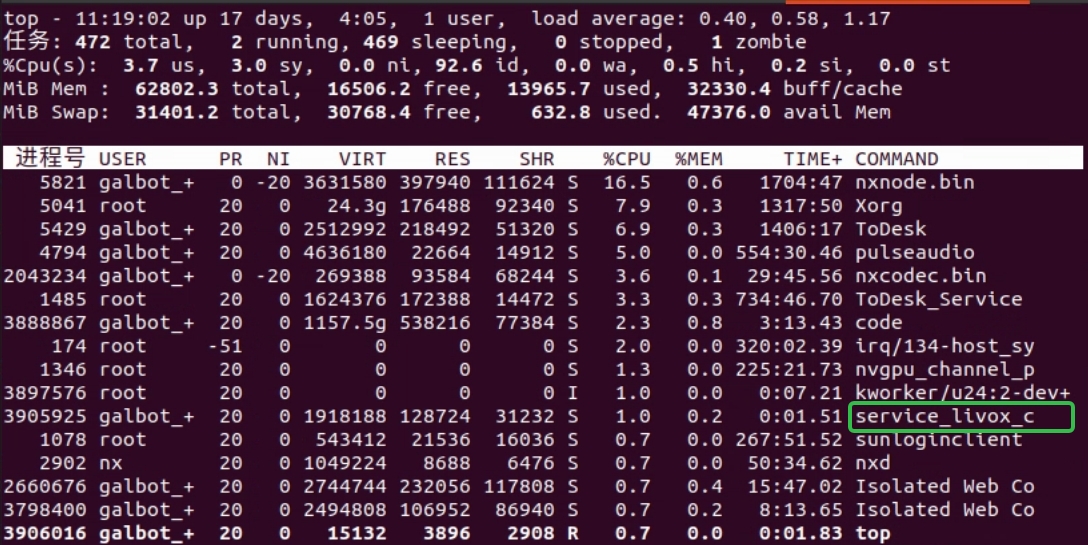
If the LiDAR has been automatically started, you can see a process named service_livox_capture in the process list, as shown below:
If the LiDAR is not running, use the following command to start it (do not start it repeatedly):
Ensure the map path has write permissions
The default map path is stored in the /var/maps/ directory. If the path does not exist or does not have write permissions, create the path and grant write permissions:
2. Start Mapping (Required)
Start the mapping program
- Press the robot's emergency stop button and use the Remote Controller to move the robot to the mapping start point (mapping can begin from any location)
- Execute the following command to start mapping:
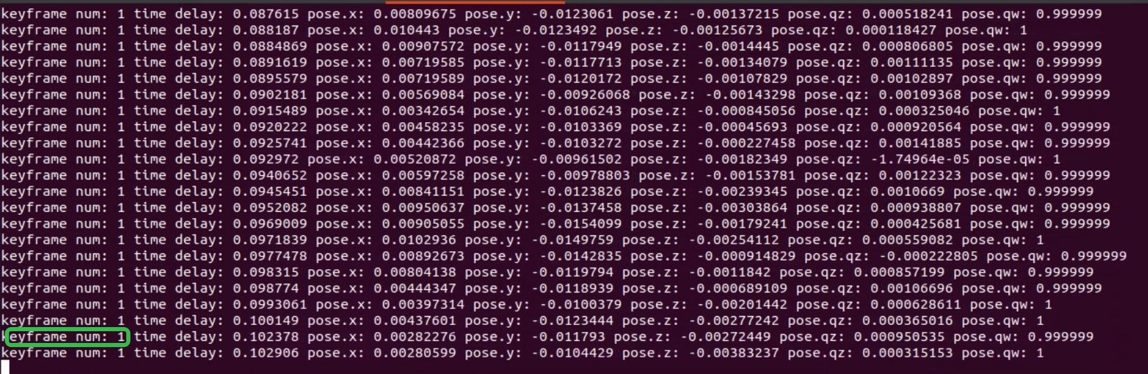
During normal mapping, the following information will be displayed: - Keyframe count (keyframe num) - Pose delay (time delay) - Current robot pose (x y z qx qy qz qw)
The keyframe count increases as the robot moves and remains unchanged when the robot is stationary, as shown below:
- Use the Remote Controller to move the robot around the environment once to build a complete map. Avoid excessive acceleration and angular velocity while moving (approximately walking speed is sufficient)
3. Save the Map (Required)
Save the constructed map
Simply stopping the mapping program will not automatically save the map. If you need to save the map, please perform the save operation before closing the mapping program.
Run the map saving tool:
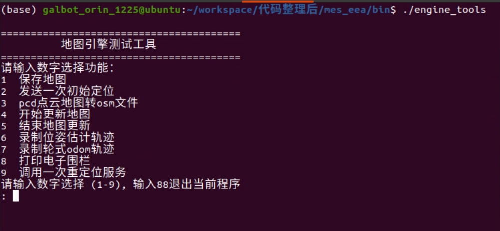
After launching the tool, enter 1 and press Enter to select the save map function. The default save path is /var/maps/room1102, as shown below:
4. Edit Map (Optional)
This step is used to optimize map quality, improving navigation accuracy and safety.
Impact if skipped
- Removing map noise: Airborne noise points in the map may cause the navigation system to misidentify obstacles, affecting path planning accuracy
- Drawing geofences: Without geofence restrictions, the robot may enter unexpected or dangerous areas
4.1 Remove Map Noise (Optional)
You need to check for noise points within the robot's operating area (from ground level up to 2.5 meters in height). Ground points do not affect navigation; the main focus is on checking and removing airborne floating noise points.
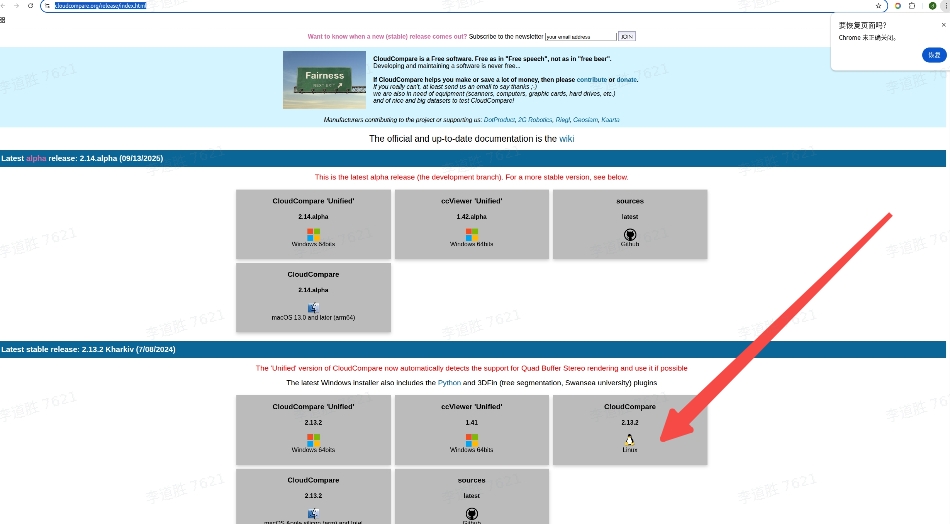
Preparation: Download CloudCompare software
Download link: https://www.cloudcompare.org/release/index.html
As shown below:
Steps:
- Open CloudCompare and drag the point cloud map
global_cloud.pcdinto the workspace

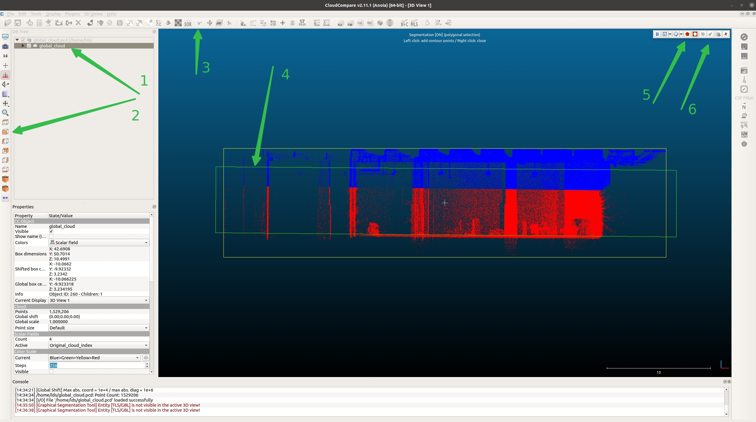
- Follow the numbered green arrows in the image below:
- Step 1: Check the file
- Step 2: Select the front view
- Step 3: Select the crop tool (scissors icon)
- Step 4: Box-select the target area (between floor and ceiling in the robot's operating area)
- Step 5: Keep the points inside the selection
- Step 6: Confirm the operation (checkmark icon)
The point cloud is now split into two parts: global_cloud.segmented inside the selection and global_cloud.remaining outside:
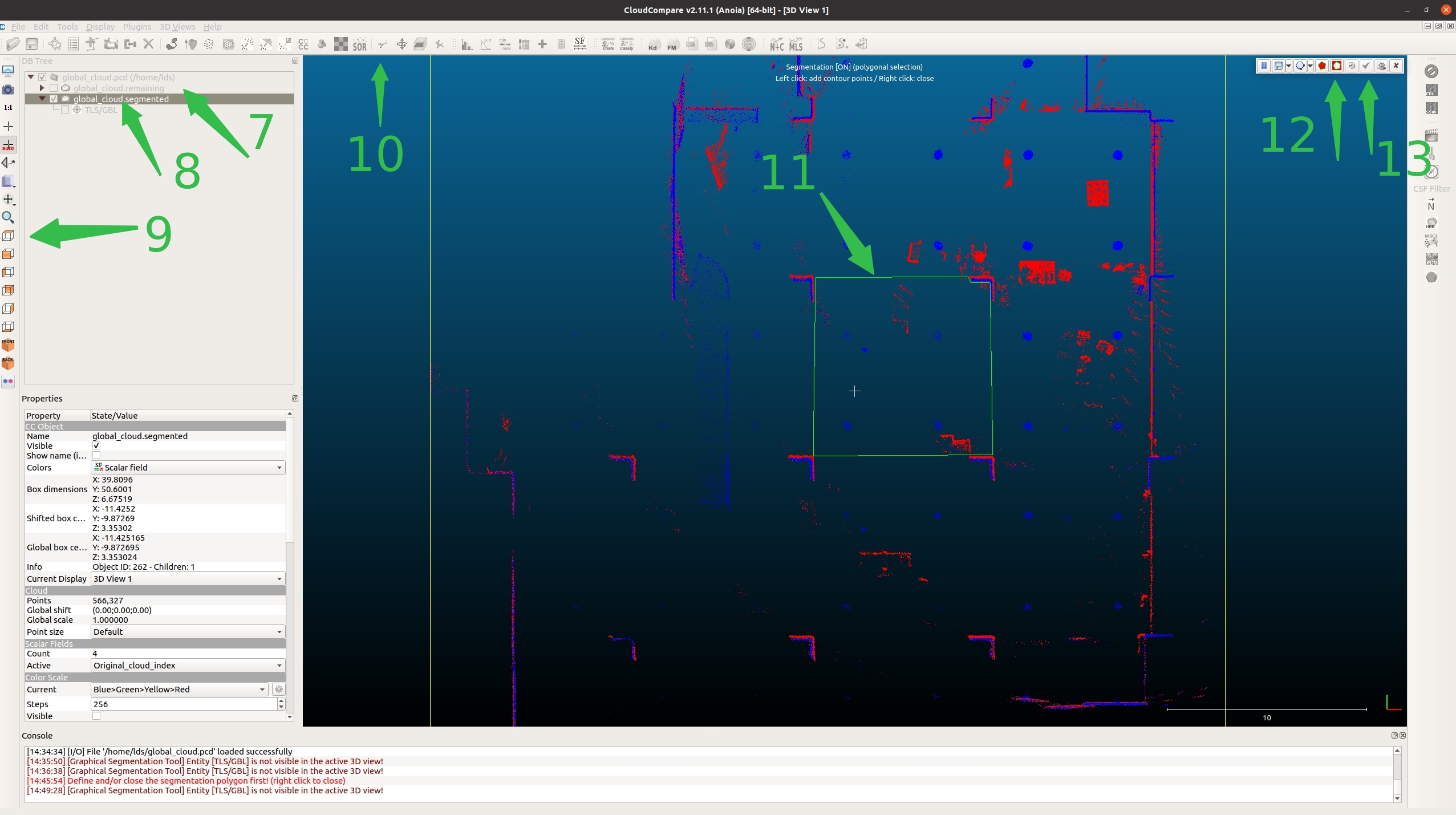
- Continue with the following steps:
- Step 7: Uncheck
global_cloud.remaining - Step 8: Check
global_cloud.segmented - Step 9: Select the top view
- Step 10: Select the crop tool (scissors icon)
- Step 11: Box-select the robot's operating area (do not select real obstacles such as stacks or tables)
- Step 12: Click the icon outside the box
- Step 13: Confirm the operation
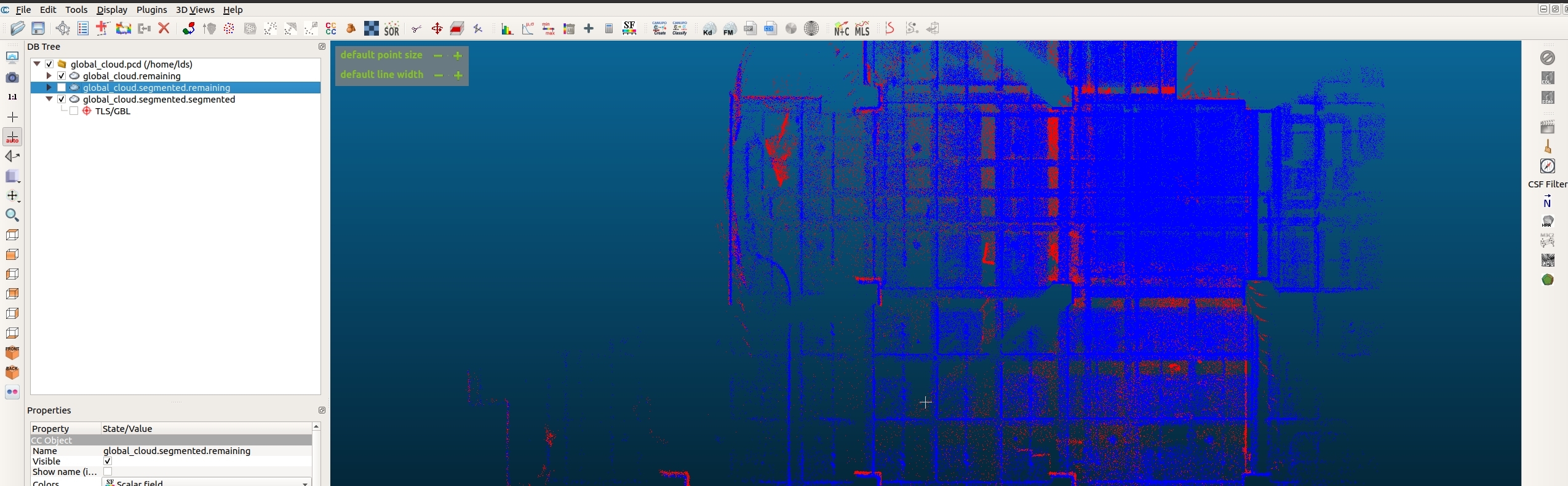
- Delete noise and merge:
- Select
global_cloud.segmented.remaining(noise portion), right-click and delete - Hold Ctrl and multi-select
global_cloud.remainingandglobal_cloud.segmented.remaining
- Save the cleaned map:
- Select Edit → Merge to merge the two point clouds
- Select File → Save to save the point cloud
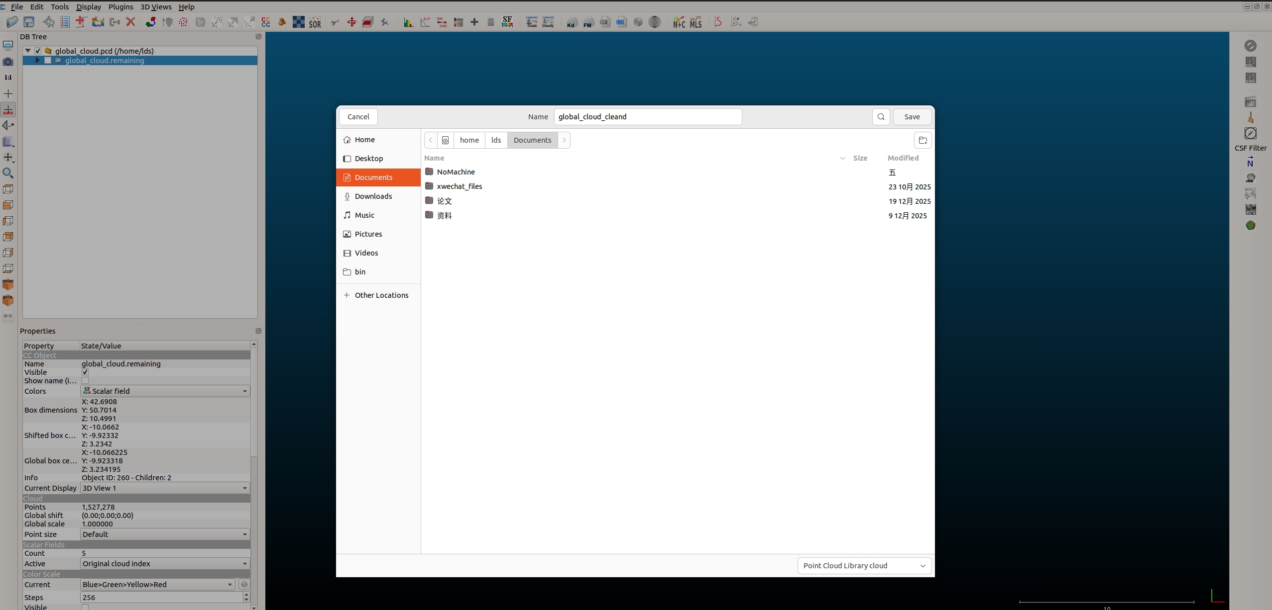
- Name it
global_cloud_cleand - Move the cleaned map
global_cloud_cleand.pcdto the map folder/var/maps/room1102/
4.2 Edit OSM File (Optional)
Draw geofences to restrict the robot's operating range, preventing it from entering dangerous or unintended areas.
Description
- Drawing geofences: Set virtual boundaries on the map to prohibit the robot from crossing fences into specific areas (such as stairs, dangerous areas, non-work areas, etc.)
- Impact if skipped: The robot can freely move to any position on the map, potentially entering dangerous or unintended work areas, posing safety risks
After mapping is complete (assuming the map is saved at /var/maps/room1102/), use the engine_tools tool to convert the point cloud map to an OSM file:
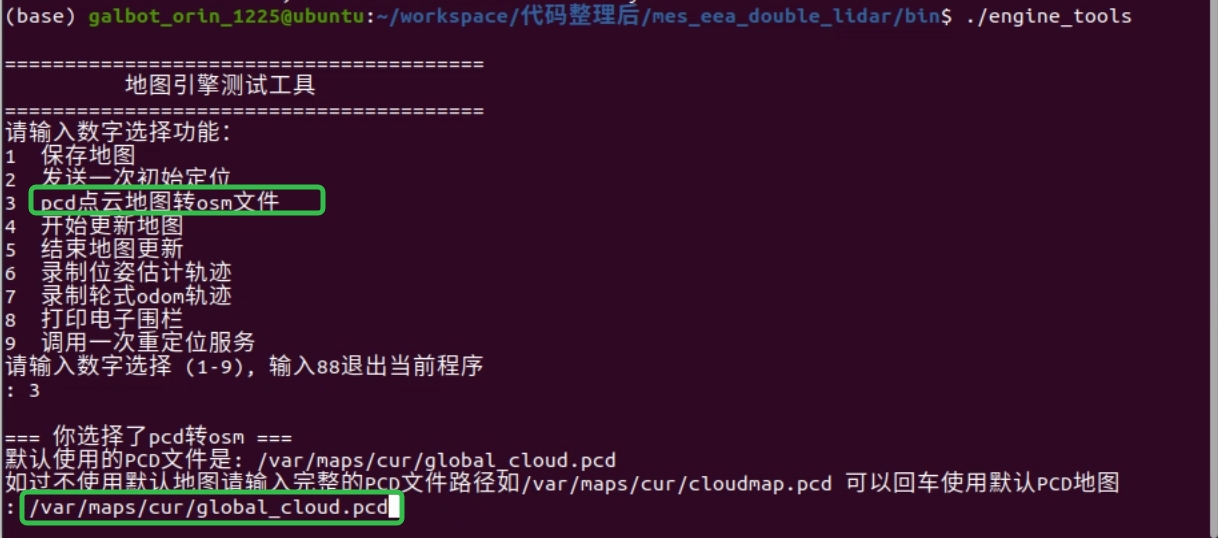
- Run
engine_tools, enter3to select the point cloud to OSM file conversion function - Press Enter to use the default map. In this example, the map is stored at
/var/maps/room1102/, so enter the full path/var/maps/room1102/global_cloud.pcdand press Enter to convert:
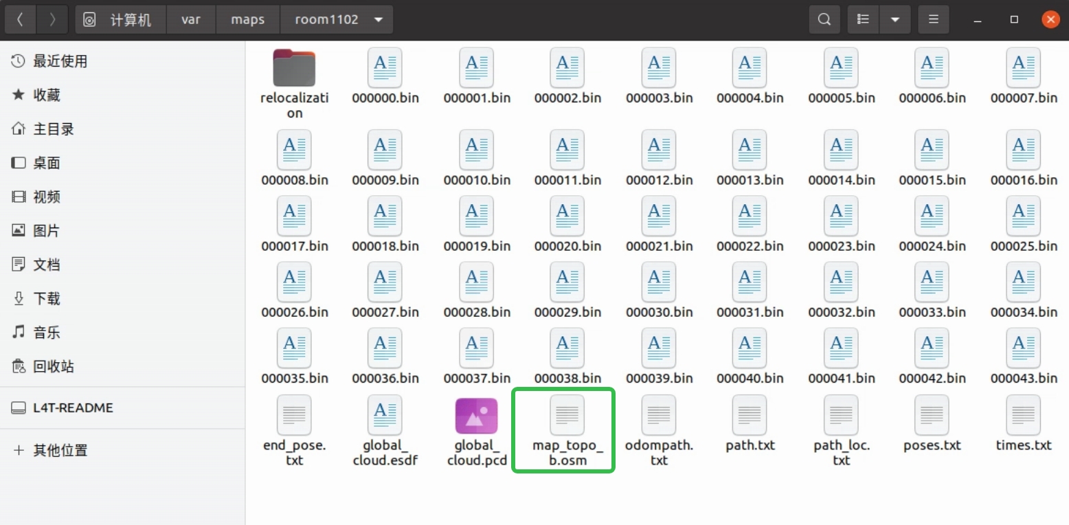
- The converted file is highlighted in green below. Open the OSM file with JOSM, as shown below:
Install JOSM (if not installed):
After installation, enter josm in the terminal to open the software.
Steps to draw geofences:
- Click File in the top-left corner, choose Open, and locate
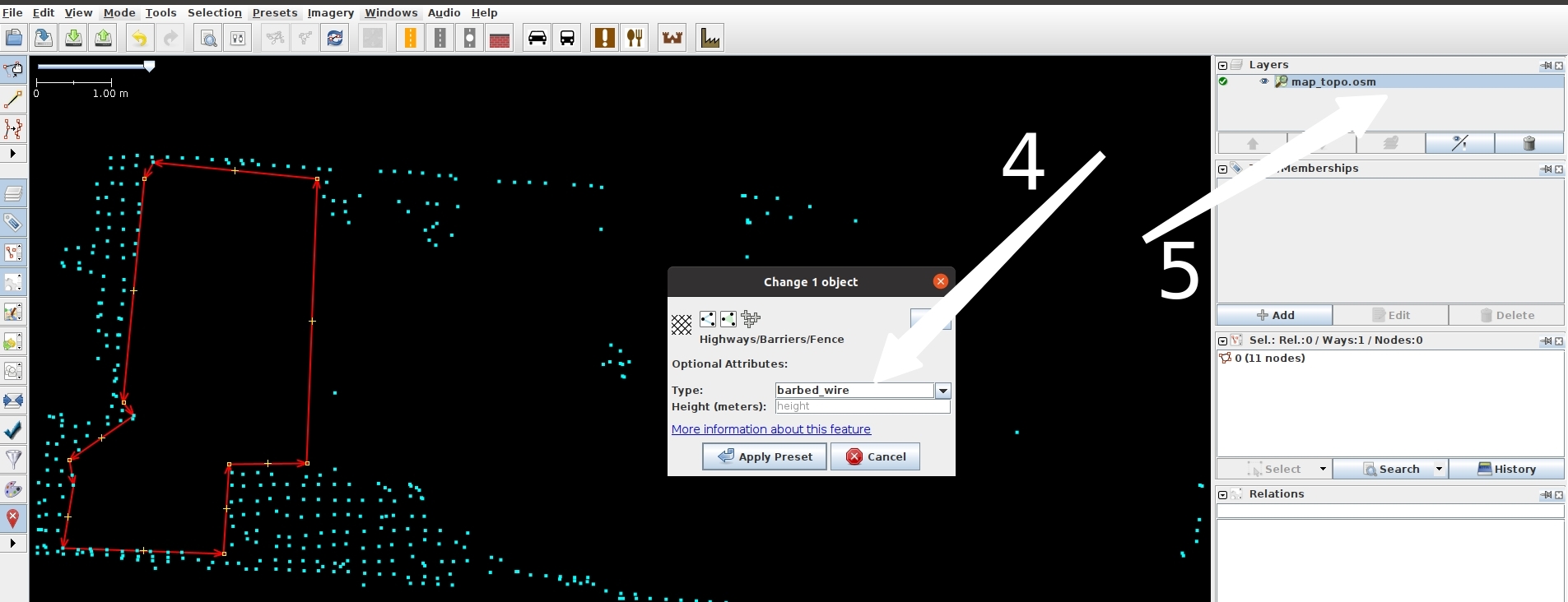
/var/maps/room1102/map_topo.osm - Select the tool indicated by white arrow 1, then left-click to draw the shape (thin red line), as shown by white arrow 2
- After drawing is complete (closed shapes finish automatically; otherwise press Esc), click the icon above white arrow 1 and select the line you just drew. The selected line turns red. Hold Ctrl to select multiple lines. Then click white arrow 3:
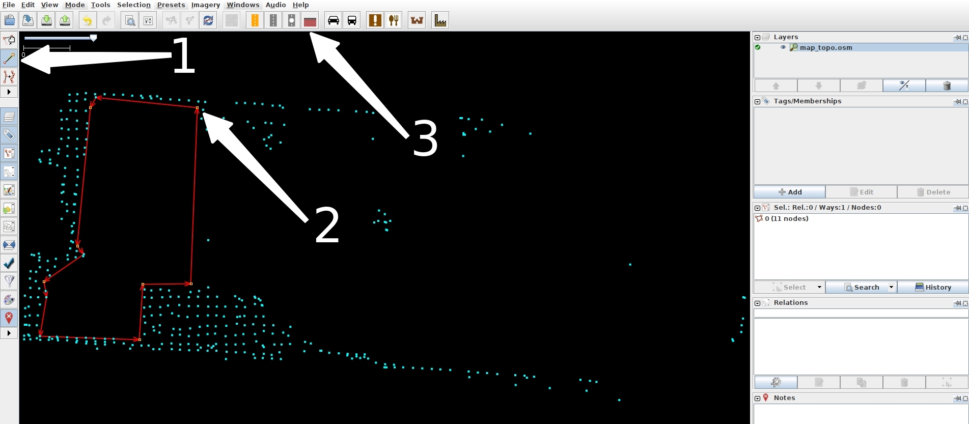
- In the pop-up, choose the Fence tab, set the type to
barbed_wireas indicated by white arrow 4, click Apply Preset, then right-click white arrow 5 and choose Save:
5. Map Update (Optional)
When the environment changes (e.g., new furniture added, obstacles moved, etc.), you can optimize the map using the map update function.
Impact if skipped
If the environment changes and the map is not updated, the robot will continue to navigate using the old map, which may lead to: - Decreased localization accuracy - Inaccurate path planning - The robot may misidentify obstacle positions
To save computing resources, the map update feature is disabled by default. You can manually enable the update switch and save the updated map:
Step 1: When localization is stable (current score > 0.9), enable the map update switch
Change manager_update_map=0 to manager_update_map=1
Step 2: Restart localization in place. Once the score returns to normal (current score > 0.9), run engine_tools and choose Start Map Update
Step 3: Use the Remote Controller to move the robot around the environment for one full loop, then run engine_tools and choose Stop Map Update
Step 4: The updated map will not overwrite the current localization map (/var/maps/cur). It will be saved to /var/maps/update_map
Step 5: After finishing the map update, change manager_update_map=1 back to 0, then replace the map if needed
Important Notes
- Both parameter changes and map replacement require restarting the localization service to take effect
- This example uses
engine_tools. If you don't haveengine_tools, use/data/galbot/bin/test_start_update_mapand/data/galbot/bin/test_stop_update_mapinstead
Localization Process
Localization is a prerequisite for navigation. Before starting navigation, you must ensure the localization service is running properly and the localization status is good.
1. Prepare the Map (Required)
The localization program requires the LiDAR to be running (it does not depend on the mapping program, so you can close the mapping program after it finishes).
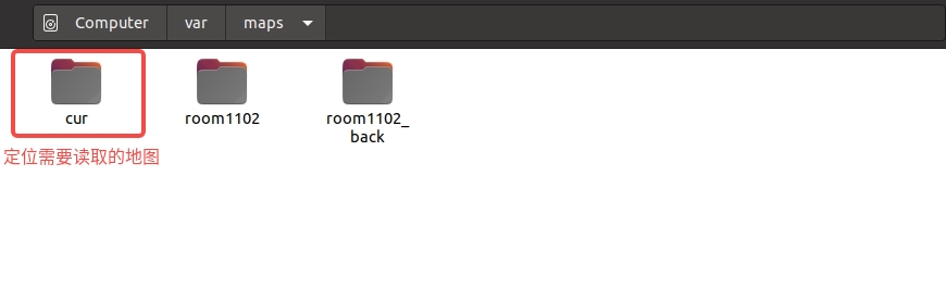
Localization uses the map path /var/maps/cur. Rename the target map to cur (for example, rename the newly created map room1102 to cur), as shown below:
2. Start Localization (Required)
Start the localization service:
3. Check Localization Status (Required)
Check localization status:
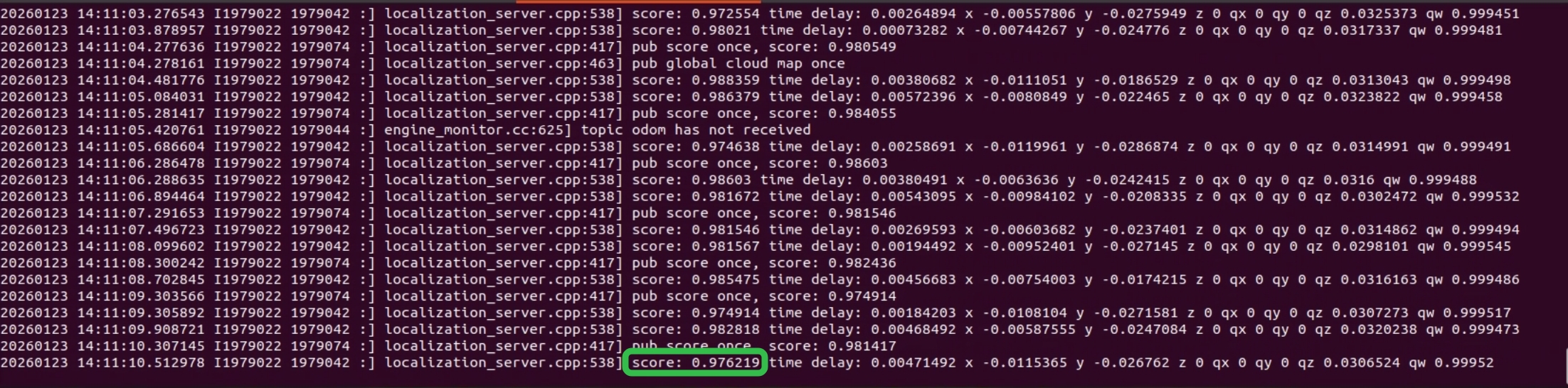
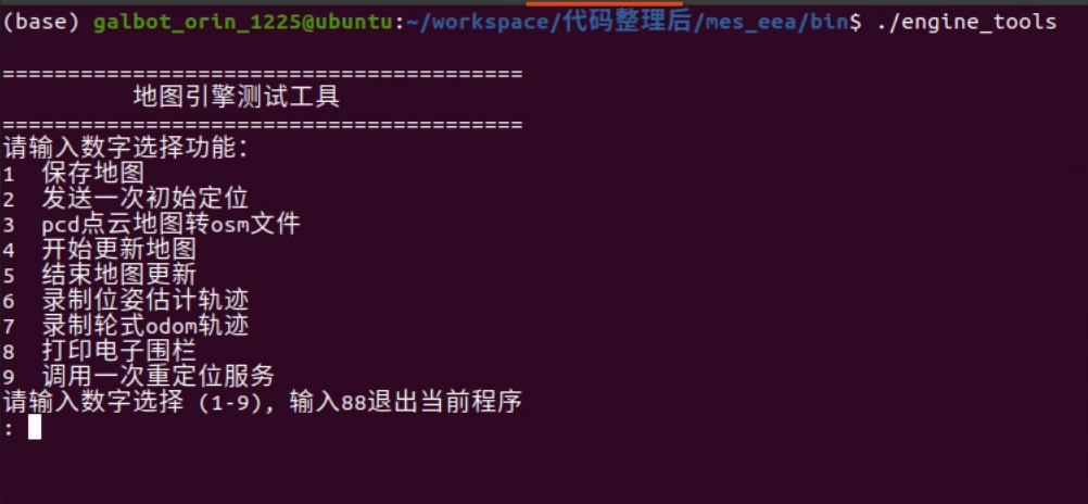
If the score is below 0.75 or no score/pose is published, use the Remote Controller to move the robot to the mapping start pose and send an initial pose once (use engine_tools, enter 2, and press Enter), as shown below:
4. Verify Localization Ready (Required)
Before starting navigation, please confirm the following checklist items:
- LiDAR service is running
- Localization service has been started
- Localization score is greater than 0.75
- Current pose is being published normally
Ready to Go
After completing all the required steps above, you can start using the robot navigation function. For details, please refer to Tutorials - Example 3. Robot Navigation.
Remote Controller Operation
The S1 heavy-duty robot uses a舵wheel steering + hub drive configuration. Due to the robot's heavy weight, manually moving the chassis is very inconvenient, so the S1 robot is equipped with a remote controller for robot movement and lift control.
Applicable users: Developers, hardware/software testers, production/packaging personnel, or any person needing to move the robot.
Control objects: Chassis movement, lift movement
Controller model: T12D
Important Notes
- The remote controller and receiver must be paired one-to-one, ensuring one controller per robot. The receiver is installed on the chassis control board (factory-default robots are already equipped and paired).
- The remote controller can only control one mode at a time. By default, all four toggle switches are at the bottom. To use a mode, push the corresponding toggle switch to the top. The chassis mode redundancy toggle switch must always remain at the bottom. During operation, only one mode toggle switch can be at the top at any time.
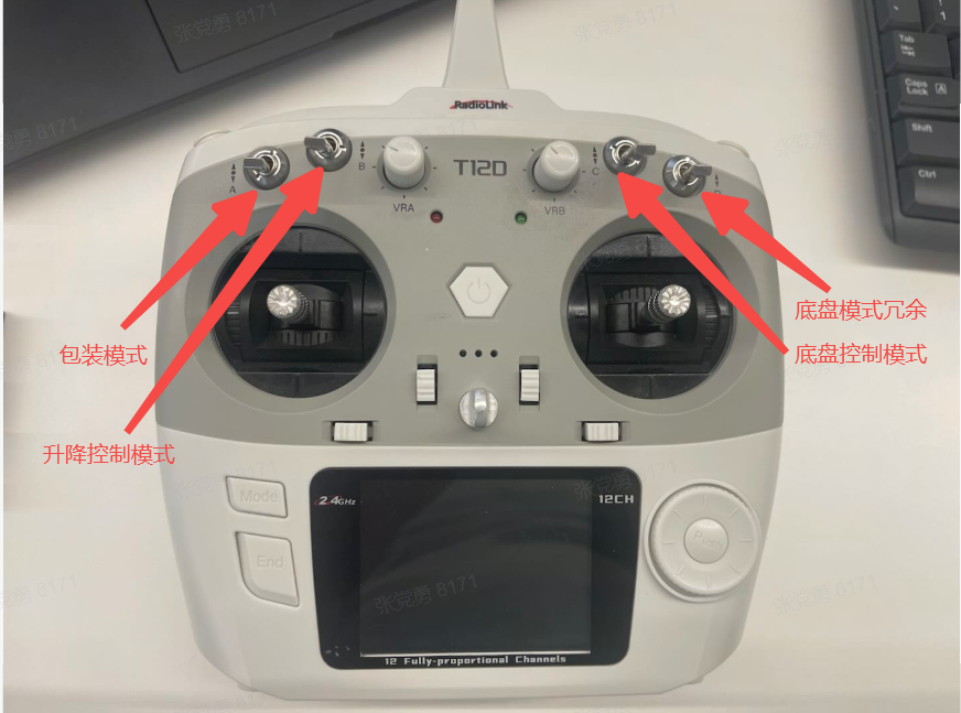
- The remote controller has the highest priority. When in remote control mode, developers and testers should close singorix to avoid unexpected lift or chassis movement after disconnecting the controller. Re-enable it after finishing remote control. Use the following command:
- After using the remote controller, turn off its power. If the receiver is online, check the screen prompt (varies by controller firmware version), select an option using the dial, and confirm to shut down.
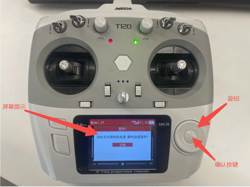
Usage Instructions
Video Tutorial
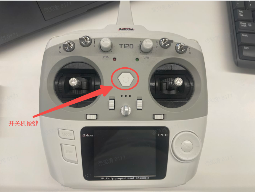
Power On/Off
- Power on: Long press the power button for 2 seconds, release when you hear beeping sounds. The green indicator light and screen will brighten after power-on.
- Power off: Reverse of power-on process.
Lift Control
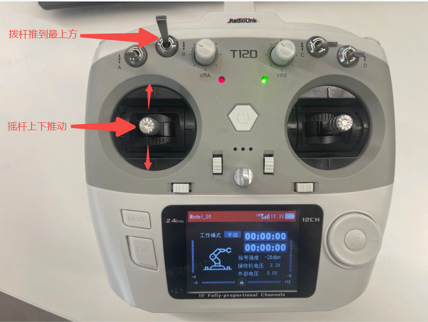
-
Push the lift mode toggle switch to the top
-
Use the left joystick to control:
- Push forward: Lift moves up
- Push backward: Lift moves down
-
The further the joystick is pushed, the faster the lift speed
Chassis Control
-
Push the chassis mode toggle switch to the top
-
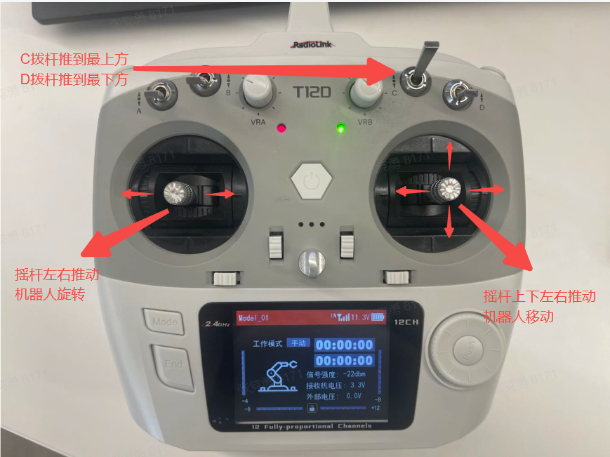
Use the left joystick for rotation control:
- Push left: Robot rotates counterclockwise
- Push right: Robot rotates clockwise
-
Use the right joystick for movement control:
- Push forward: Robot moves forward
- Push backward: Robot moves backward
- Push left: Robot strafes left
- Push right: Robot strafes right
-
Maximum speed: 0.5 m/s (linear), 1 rad/s (angular)
-
Composite motion: Pushing both joysticks simultaneously causes the robot to move and turn at the same time. Use with caution and monitor the robot's trajectory carefully.
Packaging Mode (To be developed)
-
Push the packaging mode toggle switch to the top
-
Chassis and lift are not controlled
-
The 4 wheels will point 45° outward (tbd)
-
Lift moves to a fixed height (tbd)
-
After completion, turn off the main power before turning off the remote controller
Troubleshooting
Remote controller cannot control the robot:
a. Check if the robot is in an error state - Observe if the robot's indicator light is red (red indicates error) - Observe if the robot's screen shows error messages - (Error message functionality is under development; check logs for troubleshooting)
b. Check if the robot is in emergency stop mode - Observe if the robot's screen prompts to exit emergency stop state
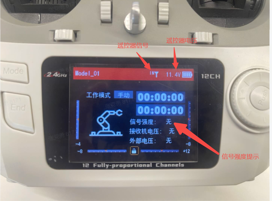
c. Check if the remote controller is working properly - Observe if the remote controller's screen has signal - Check if the voltage is greater than 6V